Gathering on-site measurements
Two methods are proposed for gathering on-site measurements:
- using a specific card, the PI2Puino (Arduino-based), which is the most easy and recommended way;
- using a simple Arduino board, like an Arduino Nano, or Arduino Pro Mini, mostly for prototyping or very small batches of sensors.
1. The PI2Puino
The PI2Puino is a very integrated board, that includes the LoRa module (with an embedded antenna), an Arduino-compatible microcontroller and a battery holder; it was designed specifically for the PI2P project, and is provided with a complete casing system.
1.1. How to get it?
PI2P is a research project, so you'll likely need to make your own boards. Anyway, if there's a local research laboratory near you that's already part of the network, you might contact them to get a small batch of boards (see https://pi2p.ird.fr/graphs/network for finding the nearest institution involved in the PI2P project). If you need to make it yourself, don't panic, as the process is quite easy, and doesn't require expensive tools.
1.2. What tools do I need?
In order to make the board, you'll need a soldering iron, and... that's it! The board was designed so that every single component on it is easy to solder, so that you don't waste your time trying to solder the boards.
1.3. How to make the PCB?
You can take two paths here: either make the board in local facilities, but please make sure to meet the minimal requirements below. Otherwise, the recommended way is to send it to a professional PCB manufacturer of your choice. For either of theses choices, you'll need, at least, to be able to respect the following criterias:
- the board needs to have a solder mask; this is because they will be exposed to harsh meteorological conditions, and a solder mask protects the copper layers for oxidation;
- for the same reasons as above, please use tainted vias when making the board;
- the minimal requirements are: 2 layers board with 1oz copper, 0.6mm trace width, 0.3mm clearance, 0.8mm via size, 0.4mm via drill.
Once you've arranged all of these requirements with your PCB manufacturer, then you can download the Gerber files here, and just send them; the board size is 97x47mm, so you may panelize it (1x2 or 2x4) to get a better price.
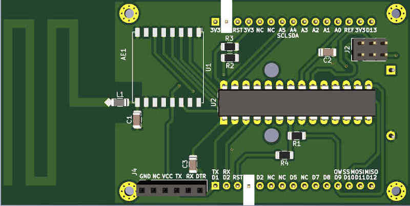
1.4. What components do I need?
The table list all the components you need, with manufacturer part number when useful, but you'll need to add the sensors you need.
| Marking | Description | Value | Package | Part N. |
|---|---|---|---|---|
| L1 | Antenna impedance matching inductance | Wire | None | None |
| C1 | Antenna impedance matching capacitor | None | None | None |
| C2, C3 | Decoupling capacitors | 100 nF | 1206 (3216 Metric) | Mainstream |
| R1, R2, R3, R4 | Pull-up/down resistors | 1k - 10k | 1206 (3216 Metric) | Mainstream |
| U1 | 868 MHz LoRa module | RFM95 | ESP-like | HopeRF RFM95W-868S2 |
| U2 | Main microcontroller | AtMega328 | DIP-28 | Microchip ATMega328P-PU |
For the impedance matching components, the value will depend on your PCB manufacturer; for a prototype, you can have a short instead of the inductance, and an open-circuit for the capacitor.
For the Atmega, some manufacturers provide them with the Arduino bootloader; you can choose them if you want to go quick, or do not have an Arduino to program the board. If it has no bootloader, then you need to populate header J2 to flash it yourself; otherwise, simply fill the holes with solder to prevent oxidation.
For the connectors, you need to populate at least J4 with a standard female pin header connector (2.54 mm); this connector is used to program the board using a FT232 module, that you'll need to buy somewhere. The two other headers, J1 and J3 are used to plug the sensors; it might be convenient, for a prototype board, to have pin headers on them; otherwise, solder the sensors' pins directly on the board.
1.5. How to assemble the board?
Once you've gathered the components and the board, you can grab your soldering iron, and simply follow the steps:
- start by soldering the four resistors and the two capacitors; the recommended method is to add solder to one side, place the component using this bit of solder, and once it's flat, solder the other side;
- then, add the LoRa module; you can start with one pin, then position the component correctly, solder the opposite pin, and it should stay in place while you're doing the others;
- you can then add the microcontroller; if you want to have the batteries on the board, you need to solder it "from the top", to prevent the solder blobs from being on the batteries casing;
- do not forget to make a short between the antenna and the LoRa module (pad L1), if you're not using any impedance-matching network;
- finally add the batteries and pins as desired.
1.6. How to flash bootloader to the board?
So now you've got a perfect board, but how can you program it? Well, first, if you choose an AtMega that has no bootloader on it, you must flash the bootloader to it. A bootloader is a small program that will allow us to program the board standalone, without using an external programmer. For this step, you'll need an Arduino, or an AtMega programmer; it is only needed once, to flash the bootloader. Start by flashing the ArduinoISP sketch onto your Arduino board :
- download and install the Arduino IDE at https://www.arduino.cc/ (v1.8.13 or higher);
- connect an Arduino board to your computer (USB port);
- open the Arduino IDE, in Tools > Port, select the appropriate port; in Tools > Board, the corresponding Arduino board;
- open the ArduinoISP sketch in Files > Examples > ArduinoISP;
- flash the sketch in Sketch > Upload.
Once you've flashed the ArduinoISP sketch, connect your Arduino ISP pins into the ISP pins of the PI2Puino; the ISP pins are a dual-row male header on the board, you should see it immediately; the pins are the same on the two boards, and look like this:
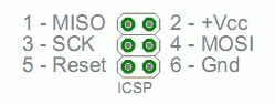
caution
Do not connect the Arduino reset pin to the ISP reset pin of the PI2Puino; instead, use pin D10 of the Arduino as a reset pin.
Once you've connected everything, plug the Arduino (you must remove the batteries from PI2Puino before), and open the IDE to install MiniCore, as documented on this page. Once installed, go to the "Tools" menu, and make the following configuration:
- board: MiniCore > AtMega328
- clock: Internal 4MHz
- BOD: BOD 1.8V
- variant: 328P/PA
- bootloader: Yes (UART0)
- programmer: Arduino as ISP (MiniCore)
Finally, press the "Burn bootloader" button, and just wait for the operation to complete (avrdude done. Thank you.); if it fails, check your wiring.
1.7. How to program the board?
Finally! You got the components, made the board, flashed the bootloader, now it's time to program it for real! To do this, you need (as stated above) a serial programming interface, for instance a FT232 module; the board as a connector (J4) that suits perfectly for this module, so just plug it in:
- PI2Puino J4 pin 1 GND to the FT232 GND;
- PI2Puino J4 pin 2 NC to nothing;
- PI2Puino J4 pin 3 VCC to the FT232 VCC;
- PI2Puino J4 pin 4 TX to the FT232 RX or the FT232 TX;
- PI2Puino J4 pin 5 RX to the FT232 TX or the FT232 RX;
- PI2Puino J4 pin 6 DTR to the FT232 DTR.
Depending on your serial module, pins RX and TX may or may not be reversed; you'll need to adapt the RX/TX matching on the board in order to program it. Then, plug your computer to the module, and upload a program using the same configuration as above. Your program should now work perfectly!

2. Alternatives
If you're looking at experimenting with the project before joining the network, then you might be interested in making a single prototype board with no overhead for development purposes. In this case, you can use any Arduino to make a demo board.
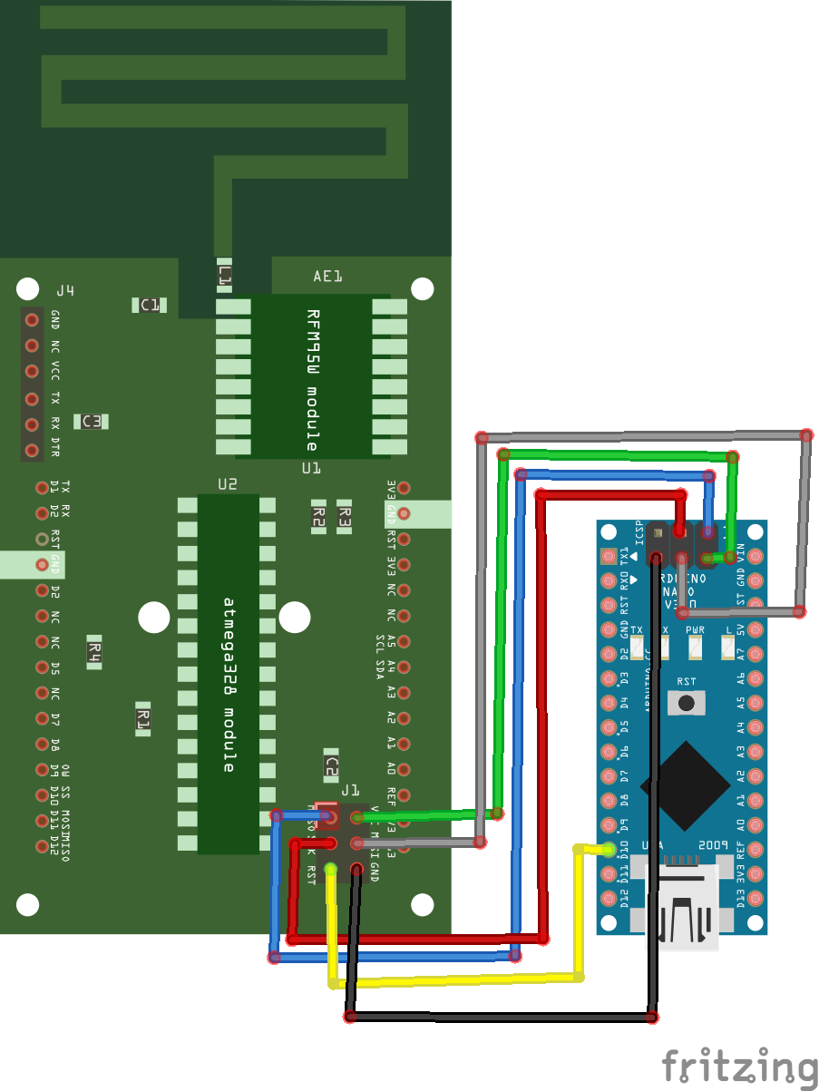
2.1. What connections need to be made?
The example below gives you a way to connect the RFM95 to an Arduino Nano; you can use any kind of board, if it is 3V3-compatible. Once the RFM95 is connected, you can connect any sensors you like, and connect the batteries you need.

3. Adding sensors and programming the board
Once your board is ready, you'll need to connect sensors to it; this section aims to explain the three simple steps to do it:
- generating an encryption key;
- copying the example code, and making it run;
- adding custom sensors.
In this section, you're supposed to have downloaded the entire Task03 directory of the main Github repository.
3.1. What are the required dependencies?
You need to install the following modules; to do it, simply download the ZIP from Github, and unzip it into you Arduino/library directory:
3.2. How to generate a key?
Communication between the board and the gateway is encrypted; in order for this encryption to work, you'll need to generate a secured key. There are several ways to do this, an one is to use this random hexadecimal generator, and generate 16-digit codes; for example, we'll take "123456789ABCDEF0".
Now get the SIT key expansion algorithm, insert your key, splitted into 2-digit blocks, in the key variable, compile the code and run it. For instance, on GNU/Linux, you can use gcc:
You should get something like: Expanded key: 55BA BDCC 410C 4C2F E555, which is your expanded key; keep it in mind, as you'll need to configure it on both the gateway and the sensor board.
3.3. How to configure the demo?
Once you've downloaded the entire Task03 directory, copy the files sit.c and sit.h from sit_final into the rfm95_arduino directory, and rename sit.c into sit.cpp. When this is done, you can open the rfm95_arduino code inside the Arduino IDE.
First, begin by adding your expanded key after uint16_t key[5] = in the Arduino file; this will ensure proper encryption on this side. You can then compile and upload the sketch, as documented in 1.7. You should see no error, and your board is now sending data!
3.4. What are the default sensors?
In the given Arduino sketch, two sensors are preconfigured: a DS18B20, that you'll need to connect to the OW (or D9) pin, and a DHT11/DHT22, that works using some custom protocol, so it is connected to D7 but you ca easily change this pin.
3.5. How to add custom sensors?
The demo provides very useful functions that you may want to use in order to add custom sensors to the board; usually, you will start with a library setup inside the setup function. Once it's done, you can do the measurements at the beginning of the loop, and send data at the end - before going to sleep, take for example this loop code: